

Formula Student is a worldwide project for engineering students to design, build and race a small single-seater racing car. Of course, we know this, but what is involved in taking a part from idea to flesh and metal? Let’s examine this question using the uprights as a case study.
So, let’s go over the basics. We’re setting out to make a car that can perform as well as possible using as little as possible.
 This demands a lightweight vehicle without sacrificing performance. To achieve this almost every component in the car must be made very stiff. These parts have to withstand high forces and moments while providing adequate strength and stiffness under various loads.
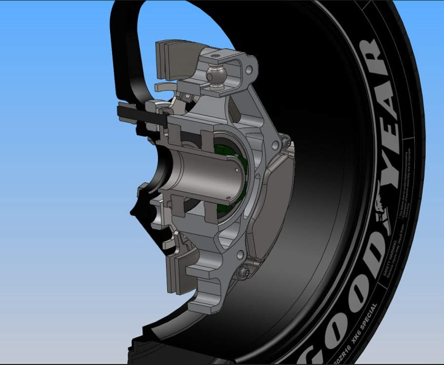
For this reason, some components need to be lightweight in order to keep the total weight of the car as low as possible. One of such components is the uprights. It carries the power thrust from the tie rod to the stub axle. Which requires it to be very strong and rigid while being as light as possible.
The front upright is one of the key elements of a racing suspension assembly, connecting the suspension link control arm, tie rod, and steering rod. The main function of the front upright is to transmit all the forces and moments between the wheel and the control arms.
An important factor of the uprights is tackling the forces generated at the tire contact patch during various manoeuvres of the car. These forces are transferred to the chassis through the suspension links. Calculating the forces on every link is important to design the suspension system as all the forces from the wheel to the chassis are transferred by the suspension linkages.
 To calculate the forces we draw a free body diagram of the loads on an upright to simplify the loads to the normal component, lateral component and a longitudinal component. We assume the ‘worst-case scenario’ for the load transfer as braking and cornering. Adding a safety factor to these calculations is essential as the dynamic loads will always be higher than the static analysis.
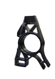
Topology optimization is used to determine which portions of the uprights can be removed to reduce the weight while keeping it safe and reliable during the load transfer process.
We start off with a “blank” and run simulations on it. Then we use nTop software to figure out what the optimum shape and size of the part needs to be. We then reduce the mass using the software to get the cut-outs in the part.
The proper structural optimization of the front upright could result in a mass reduction by 60.43% while also meeting the performance requirements.
 Our uprights will be made on a three axis CNC mill. Hence, it is vital to know if the parts can actually be machined, which we bear in mind during designing, running tests with CNC software to ensure passes are minimised.
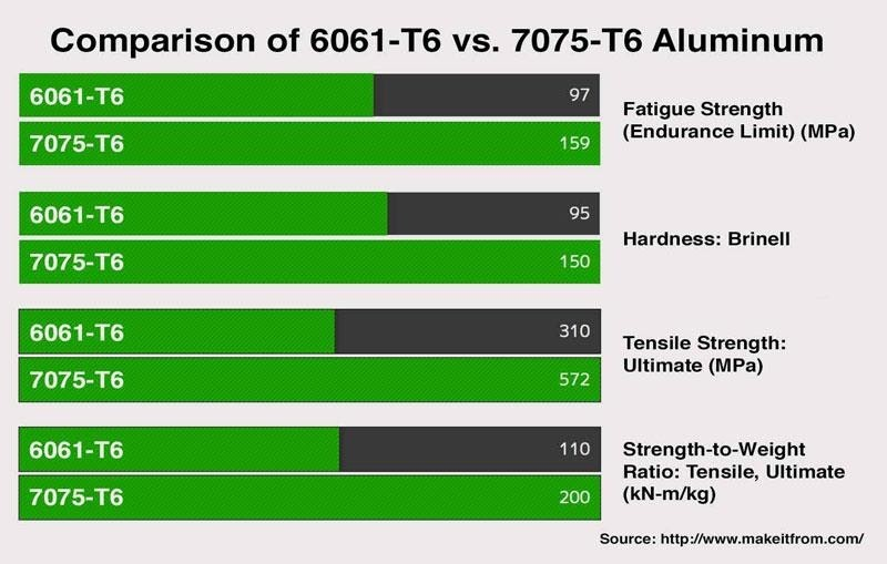
Uprights are usually made from aluminium to keep the unsprung weight as low as possible. Other benefits are aluminium’s low density compared to steel and the good manufacturing behaviour that presents in convectional subtractive processes compared to titanium. Although the 7075-T6 grade Aluminium is more expensive than 6061, we plan to use 7075 as it is stronger in comparison.
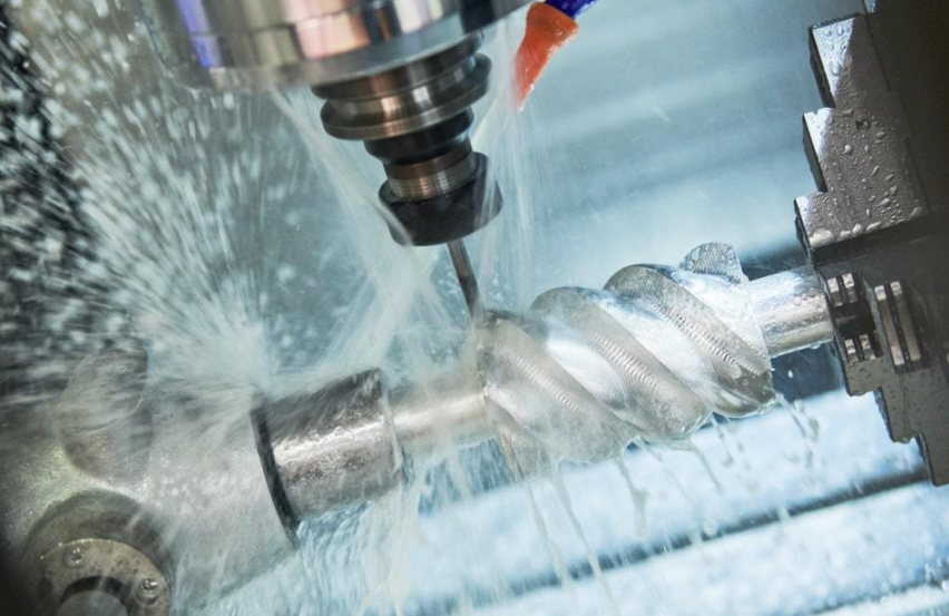 Now, we set the CNC mill to work. It is a programmable machine that is capable of performing the operations of machining with G-code. It uses a subtractive fabrication method that typically employs computerized controls to remove layers of material from a stock piece.
However, 3D printing has currently gained a lot of attention in the industry and is one of the fastest-growing and promising manufacturing technologies. It was found that, in the case of Additively Manufacturing the part, less than half of the material is required when compared to the traditional CNC milling process.
That’s it for today, do come back next Tuesday to find out more about building a car from scratch!